Simulation & CAD-to-Path
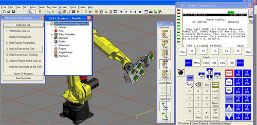
Motion Controls Robotics uses a variety of robotic simulation software tools to help customers visualize systems and determine cycle times, cell layout and longevity estimations. Using 3D CAD, ROBOGUIDE® and Extend simulation software, we can prove out different concepts for your robotic cell or entire lines to ensure a return on investment, with very little up-front cost. Motion Controls Robotics uses FANUC’s ROBOGUIDE® family of offline robot simulation software products to emulate your robotic cell. FANUC robots are exactly modeled and operate on a Virtual Robot Controller, allowing the user to precisely simulate a robotic process in 3D virtual space or conduct feasibility studies for robotic applications – without the physical need and expense of prototype work cell setup.
Motion Controls Robotics also uses FANUC Robotics’ MotionPRO™ to optimize robot motion and reduce cycle time by as much as 5 to 20 percent, as well as a significant amount of teaching and touch-up time.
MotionPRO Software Features
- Optimizes cycle time by automatically adjusting motion parameters such as speed and acceleration
- Achieves cycle time reduction with intuitive methods
- Maintains the actual robot path for any desired program speed while passing through all the taught points within a specified tolerance
- Displays the actual robot path in 3D

CAD-to-Path
Drastically reduce programming time by using comprehensive CAD-to-Path programming. Just define a feature line on a CAD model to quickly generate programs using the feature line information. This can eliminate hours of programming time and allows users to easily create robot paths from CAD data. CAD-to-Path supports generation of programs for coordinated motion, remote tool center point, multi-arm and other configurations. Motion Controls Robotics uses CAD-to-Path to import 3D drawings of existing parts, fixtures and grippers, build system layouts and to evaluate system operation. A user defines the process requirements on the CAD model, and ROBOGUIDE® automatically generates the robot program. Import unique CAD models of parts, create a work cell including machines, part transfer devices and obstacles, and teach robot paths to simulate the operation and performance of a robotic application. Reach verification, collision detection, accurate cycle time estimates and other visual system operations are simulated in ROBOGUIDE’s® unique and graphical virtual environment.
Simulation Software Features
- CAD-to-Path Programming – Easy creation of robot paths from CAD data. A user defines the process requirements on the CAD model, and ROBOGUIDE® automatically generates the robot program.
- The Process Navigator – A fully integrated environment with graphical user interface that guides new and experienced operators quickly through the steps needed to setup and simulate a cell.
- The FANUC robot library – Quick access to any FANUC robot for system layout and simulation. Each robot model comes complete with an associated Virtual Robot Controller and a unique robot solid model to replicate the robot’s operation as precisely as possible within a simulation environment.
- Built-in CAD models – Instant access to many commonly used fixtures, tables, conveyers and end-of-arm tools. Additional simple 3-D geometric shapes are provided as modeling tools to create custom machines, tools and/or fixtures.
- CAD Import (IGES files) – CAD models of existing parts, fixtures and grippers can be imported directly into ROBOGUIDE® to build system layouts and to evaluate system operation.
- Simple robot teaching – Easy creation of robot paths by teaching positions on the part model(s) or by entering robot coordinates manually. An innovative robot programming drag-and-drop Teach ToolTM is combined with a traditional teach pendant style jogging panel.
- Simple robot instructions – Standard teach pendant instructions are supported by ROBOGUIDE® to develop teach pendant programs for throughput verification.
- Robot reach check – A 3-D view of the robot work envelope that helps the user to layout parts, fixtures and other cell components effectively within the work cell.
- Cycle time validation – Calculated, accurate cycle time data is generated by running the taught robot program in simulation mode.
- Collision detection – Visual identification of collisions during robot simulation allows the relocation of the robot, tooling and/or parts before the robot is installed in the plant.
- Profiler – The teach pendant program profiler allows programs to be reviewed quickly for timing bottlenecks and operational slowdowns. Processing problems are solved before the robot is placed into production.
- TP Trace – A unique capability to display the actual robot motion versus the taught path on the teach pendant display. It includes a teach pendant trace by speed, orientation and acceleration, allowing touchup of the robot program before the robot is deployed.
