FANUC’s Snap-in-Motion is a high speed vision function available for robotic pick and place applications.
Robotic pick and place applications sometimes require picking randomly positioned parts and placing these parts in a precise position and location. This is done using a camera and FANUC’s iRvision 2D software option. iRVision 2D can detect a part’s X,Y location on a work surface as well as calculating the part’s rotation.
2 Types of Traditional Robotic Pick and Place
- The robot snaps an image of the part, then moves to the correct location to pick it. (Fixed Frame Offset)
- The robot presents the part to the camera, then the image is snapped and the offset is generated. (Tool Offset)
The traditional vision process for this type of pick and place application would be:
- The robot stops,
- an image is captured,
- robot continues along the path to the location above the final place,
- part is turned using the robotic wrist to the correct position,
- and finally, the part is placed in its final, correct position.
Adding this type of vision process to a robot system increases the flexibility of the system and can eliminate the cost and space that accompanies adding special fixtures.
Although, there are times when the required rate of the robot system cannot be met when all the above steps have to be taken. This is where FANUC’s Snap-in-Motion function becomes the best solution. By running the robot and camera using the same controller, Snap-in-Motion captures an image without stopping the robot. Through this added benefit of the Snap-in-Motion feature, overall cycle time can be reduced because the vision aspects are happening in parallel.
How does Snap-in-Motion work?
As the name implies, the camera(s) used for the vision process can take a picture while the robot is moving the part. Accomplishing this goal requires upfront programming and setup:
- The type of camera mounting needed is determined:
- Robot-mounted
- Fixed camera
- Camera mounted on another robot (only one robot can be moving during the image capture)
- Next, the programmer must set the exact robot position and speed for the snapping moment.
- Finally, a fixed frame offset is developed for measuring the part position, so when the image is snapped of the part the robot knows how to correct the position (in motion) before placing.

Snap in Motion can be used for:
- 2D Single-view Vision – The basic program using one camera.
- 2D Multi-view Vision – This supports the use or more than one camera when larger parts are not able to be captured in a single view.
- Depalletizing Vision – This process supports one camera used to estimate height based on the size of the part.
What about Motion Blur?
Everyone has had the experience of taking a picture of something in motion, and the image comes out blurry. This motion blur can also happen with Snap-in-Motion. This means that some of the camera settings that would be used for a traditional pick and place image capture need to be changed.
- Perfect exposure time using this equation- (Pixels) = V x T x N / S
- Increase lighting
Example of Snap-in-Motion Application:
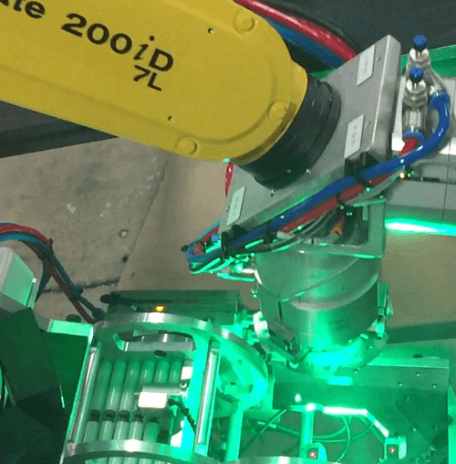
- Parts are quickly coming down a chute and landing in different positions each time.
- The part has multiple holes and needs to be positioned correctly so these holes line-up with the rods on the other assembly.
- The camera is mounted on the chute. The part is picked and an image is snapped.
- Then, as the robot moves the part to the assembly area, the wrist turns the part so it will align perfectly.

