How to Robot Article
The robot stopped.
What happened first?
A FANUC alarm gives you a starting point. The alarm history helps you understand the sequence. Use both to investigate the stop, document what happened, and reduce repeat interruptions.
Read the alarm. Check the sequence.
- Capture the active alarm.Record the full code, message, and any additional details before resetting. On many FANUC pendants, select MENU → ALARM to open the alarm screen.
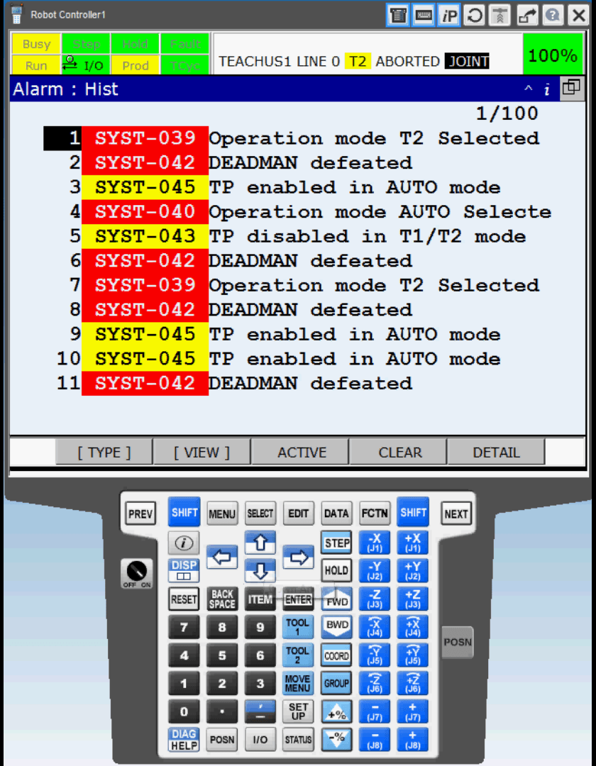
- Review the alarm history.For the R-30iB controller family covered by FANUC’s alarm manual, history displays up to the last 100 alarms. Look at the entries around the stop. Several alarms may follow one event, so identify the earliest relevant entry rather than assuming the last message explains the cause.
- Open the description and help.Use the alarm detail/help functions available on your controller. On the pendants shown in the video, SHIFT + DIAG/HELP opens troubleshooting information when the Alarm Cause/Remedy function is available. Confirm the procedure in the manual for your software version.
- Check the rest of the cell.Compare the robot alarm with HMI or PLC messages and the operating condition. A robot stop may involve tooling, material flow, communications, or another part of the system.
Before restarting: Follow the cell’s approved recovery procedure and address the cause before resetting. Use qualified personnel and required energy isolation for inspection or repair. Do not bypass safeguards to clear an alarm.
FANUC alarm navigation walkthrough
Use this MCRI video as a visual reference for active alarms, history, help, and reporting on the controllers shown.
This earlier walkthrough includes R-30iB Plus screens. FANUC now also offers the R-50iA controller family. Menu labels, history capacity, help functions, and reporting availability depend on controller, software, and installed options. Watch on YouTube.
Two FANUC alarms, explained
These examples show how to move from an alarm message to its cause and the documented recovery steps. Follow the instructions for your controller and your cell’s approved restart procedure.
SRVO-002
Teach pendant E-stop
Cause: The pendant’s emergency-stop button has been activated.
- Open the active alarms.The fault code appears in the pendant’s status area. Select MENU → ALARM to review the active messages. In the original walkthrough, ALARM is menu item 4.
- Review the history.Select F3 (HIST/HISTORY) on the pendant shown. Review the entries around the emergency stop to see which other alarms occurred.
- View the cause and remedy.Highlight the relevant alarm and use SHIFT + DIAG/HELP where supported to display its explanation.
- Follow the documented recovery.Once the reason for the emergency stop has been addressed and restart is permitted, turn the pendant’s emergency-stop button clockwise to unlatch it. Then use RESET.
If it will not reset: FANUC’s R-30iB alarm-code and maintenance manuals list replacing the pendant as the next remedy. Have qualified maintenance or MCRI service handle further diagnosis and replacement under the applicable maintenance procedure.
SYST-042
DEADMAN defeated
Cause: The enabling switch, labeled DEADMAN in the alarm message, was being held when the operating mode changed from T1 or T2 to AUTO.
- Open the alarm screen.On the R-30iB Plus pendant in the walkthrough, select MENU → ALARM.
- Select the history.Choose HISTORY from the top menu and use the arrows to select the SYST-042 entry. A previous alarm can be investigated even when no active alarms are present.
- Open the diagnostic help.Use SHIFT + DIAG/HELP where supported to read the cause and remedy for the selected fault.
- Release the enabling switch.FANUC’s listed remedy is to let go of the DEADMAN switch, then use RESET. The switch should be released when changing to AUTO.
Terminology: “Deadman switch” is the wording used in this FANUC alarm. It refers to the teach pendant’s enabling switch.
Which alarms keep coming back?
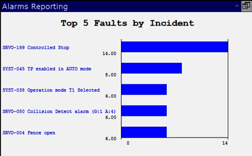
On controllers equipped with the Fault & Incident Report option, the reporting screen can help identify frequently occurring faults. In the R-30iB Plus example shown, select MENU → ALARM → F1 (TYPE) → REPORTING. The INCIDENT view ranks the top five faults by occurrence count.
The function also offers total-time and longest-time views. FANUC documents these fault durations as the time between an alarm occurring in AUTO and its reset; this does not necessarily equal the full production interruption. Compare the reports with your cell’s downtime records. A frequent, brief stop may need a different response from a rare stop that takes hours to resolve.
Build a record that helps the next shift.
For recurring alarms, record enough context to compare events and confirm whether a correction worked.
What happened?
Alarm code and message, date and time, robot or cell, and the relevant history entries.
What was running?
Product or recipe, cycle step, operating mode, and any recent changeover or maintenance.
What resolved it?
Downtime, checks performed, corrective action, and whether the fault returned.
From alarm history to a faster answer
FANUC’s Error Code Output option can provide detailed alarm information to a PLC. With the right controller options, data collection, and integration, alarm records can become part of a broader view of cell performance.
An AI interface connected to those records could help your team ask:
- “Which alarms repeated during the last shift?”
- “What happened just before the cell stopped?”
- “What did maintenance document the last time this occurred?”
The value is quicker access to recorded information, through text or voice when useful. Answers should link back to the underlying records and approved documentation. Available answers depend on the data collected; diagnosis and recovery still require the appropriate technical review.
Know when to bring in support
Send the details. Shorten the investigation.
If an alarm persists, returns after recovery, or needs further diagnosis, send MCRI the information that helps us understand the system:
- Robot model, F-number or serial number, and MCRI job number if available
- Controller and pendant type, plus software version
- Full alarm messages, history screenshots, and related HMI messages
- What the cell was doing and what changed before the stop
- Checks already completed and their results
If parts are needed, confirm the component and part number with the service team before ordering. An alarm code alone does not establish which component needs replacement.

MCRI service & spare parts
Need help with a recurring FANUC alarm?
Share the alarm history and what was happening at the cell. MCRI can help investigate the issue and identify service or spare parts needs.
Contact Service 419.334.5886 · service@mcri-us.com