A Palletizing Machine-Dual M-Stack
As an advanced industrial automation palletizer, the Dual M-Stack delivers reliable, high-speed palletizing across two product lines. This system is…
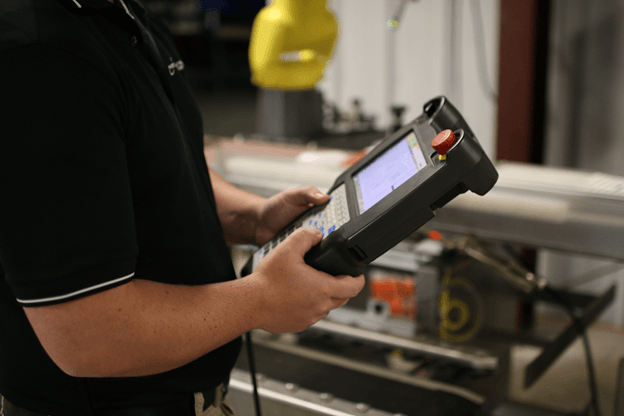
Read ArticleThis How-to article is going to go through using the FANUC teach pendant to switch the state of robot cell outputs and simulate and verify inputs for troubleshooting purposes.
A robot cell is a complicated system of processes working together to accomplish a final goal by finishing each of these various tasks. Many of these processes involve inputs and outputs:
Example of Inputs on a FANUC Teach Pendant
|
Examples of Outputs on a FANUC Teach Pendant
|
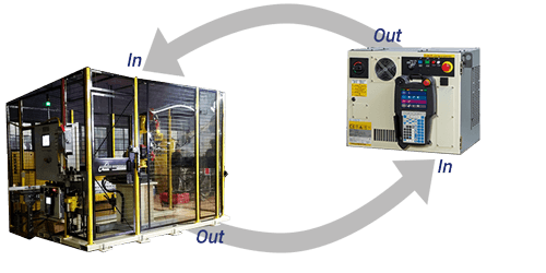
Input-Output Model
|
There are times when one part, like a sensor, isn’t working and the operator needs to be able to troubleshoot to pinpoint the issue. This is when using the teach pendant to do I/O testing can be helpful in finding the root cause of an issue. This testing should not be done in a production environment, but for troubleshooting purposes only.
*Signals that affect safety are always active.
Let’s think about a case packing cell – in this cell, a case comes down the conveyor triggering a sensor which lifts the case to a defined angle for a perfected packing position.
Select MENU
Arrow Down to 5 I/O and ENTER
On the top menu select TYPE
Arrow down to DIGITAL and select ENTER
I/O Digital Out screen shows each output port and the status of the port.
The top menu has ON OFF button options you can select to simulate ON or OFF. The color is highlight in reverse coloring, so you know it is a simulation.
![]()
To switch from the I/O Digital Out to the I/O Digital In use the IN/OUT button on the menu.
From the Status column, you can use the arrow keys to move to the correct input and then over to the SIM column. The menu changes to give options for this column.
Select SIMULATE, arrow over to STATUS, and select ON
These can be turned off using the same process.
For Robot I/O, select TYPE from the menu and move to ROBOT and then ENTER
The I/O Robot Out screen shows each output port.
Turn the status to ON or OFF selecting the correct button
To switch from the I/O Robot Out to the I/O Robot In use the IN/OUT button on the menu.
Arrow over to SIM and select the SIMULATE button then arrow over to the STAUS column and turn it on.
These can be turned off using the same process.
Simulating Inputs/outputs should only be used for troubleshooting – do not use in the production environment. Make sure to turn off all simulated inputs/outputs