Developing and maintaining a safe robot cell is essential to protect people and equipment, and one of our main priorities when designing the system. Motion Controls Robotics promises safe robot systems through being members of the Robotics Industries Association and following the guidelines laid out by the RIA as well as having a certified TUV Functional Safety Engineer on staff.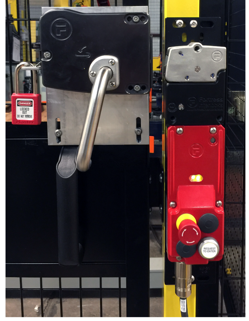
We have heard from customers that many integrators not involved with the RIA can skip or miss important aspects of safe robot systems. We have several Tech Talk articles centered around Robot safety. This week we are going to focus on:
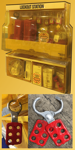
Lockout Tagout for Robot Systems
When working inside the robot cell, all equipment and/or circuits must be locked out to protect against accidental or inadvertent operation that could cause injury to personnel. Do not attempt to operate any switch, valve, or other energy isolating device bearing a lock.
For any companies planning to automate a manufacturing process, the first priority is making sure all employees are very familiar with the robot system and follow proper, documented procedures.
Training the operators and maintenance personnel working within the robot system is an ongoing process throughout the life of the cell. The primary responsibility for the proper lockout of equipment and/or circuits belong to the persons working on that equipment.
Ways MCRI helps to ensure safety:
- MCRI offers training for all personnel involved with the system. The training explains the basic safety functions and operations.
- The robot cell is designed so the operator faces the cell while working on the HMI.
- Safety fencing, light curtains, and/or sensors are put in place to define the work envelope of the robot.
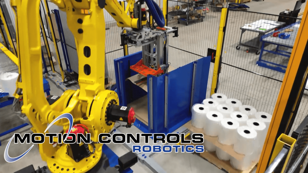
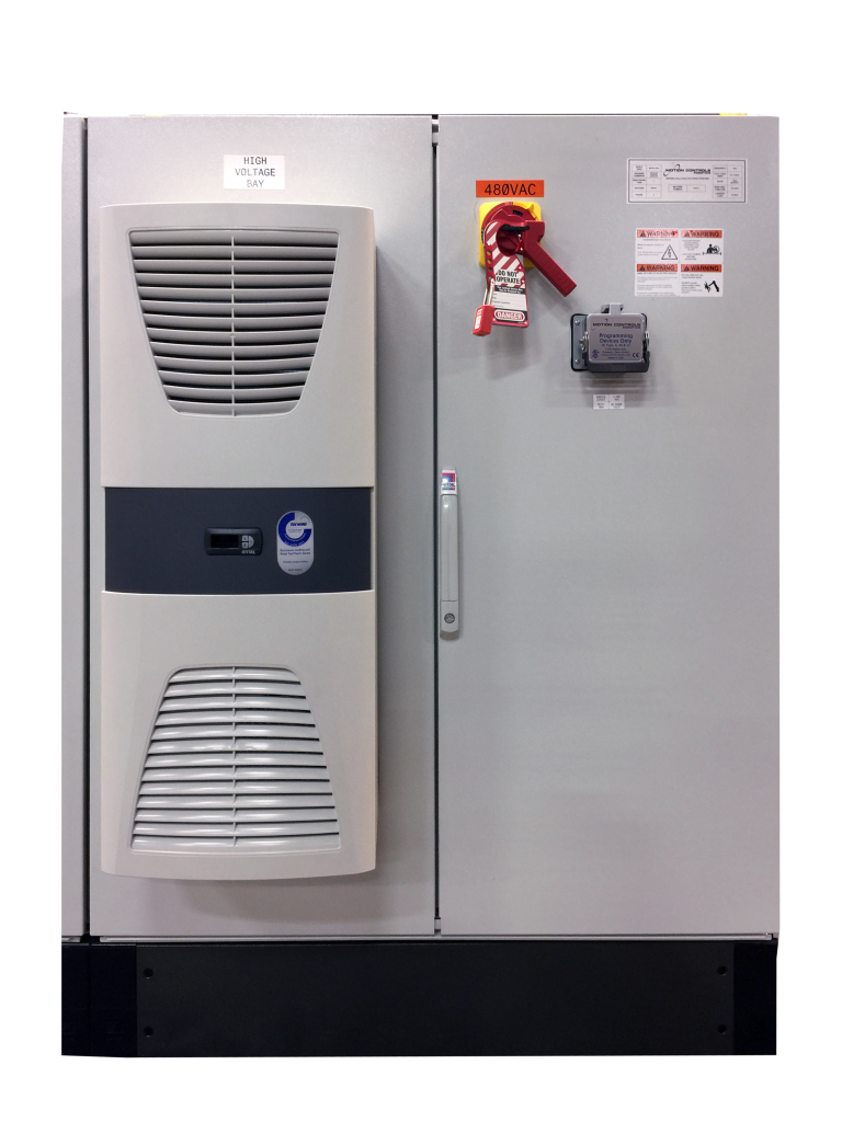
- MCRI uses entry gate lock systems on our fencing – these are dual channel control reliable. We provide a “Request to Enter” button that first, homes the system, then unlocks the gates. Once the gates are unlocked and the gate key is removed, an operator can enter the cell and the cell has no electrical power to solenoids, motors or robot servos.
 The air to the end effector is not removed because that would create a greater hazard of dropped product.
 - Our entry gate lock may have a key switch or sliding actuator key that can be locked out by a hasp and multiple locks for multiple operators.
- If complete de-energized state is required, for maintenance purposes, the main dump valve, and main disconnect can be locked out.
We recommend that there is an easy to identify lock for each person involved in the maintenance process and these locks are used to lock out energy sources.
If this is not feasible, the designated individual of the work crew (e.g. the project Supervisor or Foreman) with complete knowledge of who is on the crew is assigned as the individual responsible for carrying out all steps of the lockout procedure. That individual will inform the work crew when it is safe to work on the equipment and/or circuits. Additionally, the designated individual will not remove a crew lock until it has been verified that ALL individuals are clear.
Preparing for Lockout of Circuits and Equipment
Before lockout commences, authorization from Supervisor(s) and/or Leads will be obtained through the proper procedures.
Employees must be certain as to which switch, valve, or other energy isolating devices apply to the equipment and/or circuits being locked. More than one energy source (electrical, mechanical, or others) may be involved.
Sequence of Lockout Procedures
- Notify all affected employees and management that a lockout is required and the reason for the lockout.
- If the equipment is in operation, after obtaining approval, shut it down through the normal stopping procedures.
- Operate the switch, valve, or other energy isolating devices so that all energy sources (electrical, mechanical, hydraulic, pneumatic, etc.) are disconnected or isolated from the equipment and/or circuits. Stored energy, such as that in capacitors, springs, elevated machine members, rotating flywheels, hydraulic systems, and air, gas, steam, or water pressure, etc., must also be dissipated or restrained by methods such as grounding, repositioning, blocking, bleeding down, etc.
- All affected employees are then required to lockout the energy devices with their individual lock.
- After insuring that no personnel are exposed and as a check on having disconnected the energy sources, operate the push button or other normal operating controls to make certain the equipment will not operate. If an electrical circuit has been locked out, insure that the circuits are de-energized by applying an appropriate voltage tester that itself has been tested on live circuits. Be sure to return all operating controls to the neutral position.
- The equipment and/or circuits are now locked out.
*Special Note: In the following steps, when more than one individual is involved with the work to be completed and required to lock out the equipment and/or circuits, each employee will place their own personal lock on the energy isolating devices
Restoring Equipment and/or Circuits to Service
- When the job is complete, and the equipment or circuits are ready for testing or normal service, check the equipment and/or circuits to ensure that no one is exposed.
- When the equipment and/or circuits are clear, remove all locks. The energy isolating devices may be operated to restore energy to the equipment and/or circuits
It is important to understand that this is a guideline and that your company is responsible for developing, training for, documenting and any other requirement set forth, to provide the lock out/tag out procedure for each system.