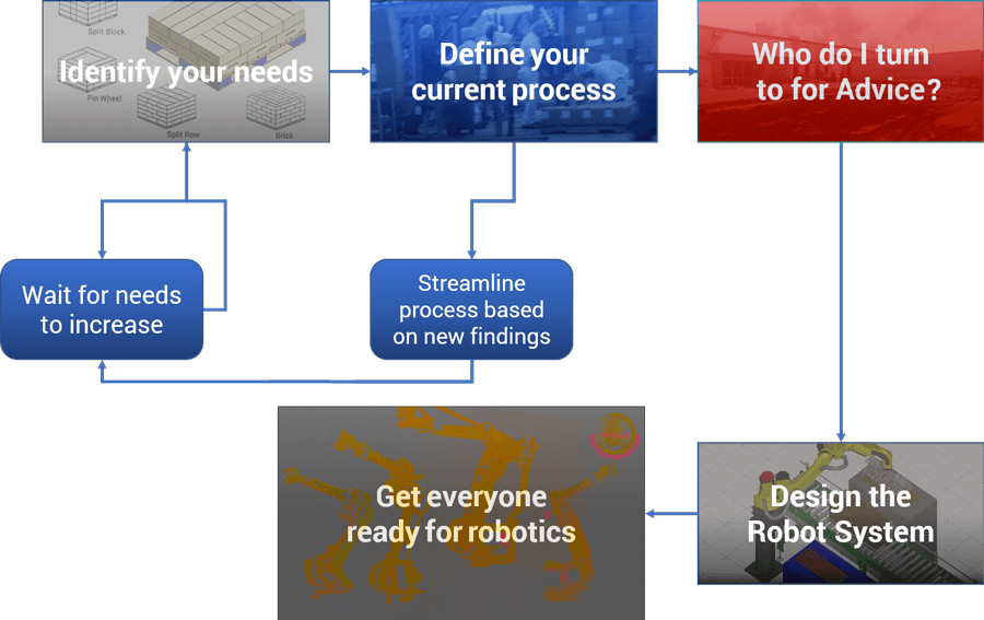
The decision to add robotics to your application has been made and you have selected an integrator. The next step is to work together to design your system.
- You already defined your current process which returned an improvement goal for your robot system (top ten improvement goals for adding automation).
- Share this information with your system integrator.
- Work together to define each area of the system based on your previously established improvement goal:
- Select the robot
- Cell layout
- Speed, precision, and payload
- Robot accessories
- System components
Selecting the Robot
Once the process has been defined and reviewed, the robot can be selected. There are a wide variety of robot manufacturers, models, and speeds.
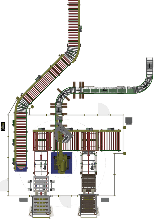
Cell Layout
Let’s start by looking at the installation area. The area for the system has been laid out, defined, and CAD drawings have been shared with the integrator.
These considerations need to be addressed:
- Layout – the space available, the cell layout, peripherals needed – what action the robot will do most often.
- Reach – what is the total reach needed for the robot
- Mounting type – how/where does the robot need to be mounted to accomplish the task
- Peripherals moving – address and define safety concerns with other moving objects
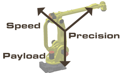
Speed, precision, and payload
Speed, payload, and precision work together in the system and are dependent on each other to accomplish your improvement goals.
Payload
The payload consists of considerations beyond just the weight:
- Inertia – resistance to change in direction of motion
- Weight/Dimension – the weight is important, but the product dimension also plays a large part
For example, you plan to install a FANUC M20iA robot that is rated for a 20kg (44 pounds) payload. Your product is 10-16-pound bowling balls. The M20iA robot can easily carry the bowling balls 6″ from the wrist but, change that highest 16-pound payload to a 3-inch diameter rod 46″ long, and you will exceed the robot’s inertial capacity even though you are still only handling 16 pounds. You can read more about this in our Robot Inertia vs Payload article.
As you approach the robot’s specified maximum payload or inertia, you may need to sacrifice a certain amount of speed in order to accurately or repeatably place the part or prevent the robot from faulting due to excess forces seen at the various joints.
Precision
As accurate as a robot is, there is the issue of momentum to consider. As the payload increases, the momentum of the part, and the robot come more into play. Moving quickly to a point and stopping can cause the robot to overshoot its destination as it attempts to settle into its designated programmed position. If the part is released or picked during this time, accuracy will suffer. Some new robots have faster processors which help with the precision issue. Precision performance can be improved by using vision or force sensors in the system.
Other items can combine for less precision in the system:
- Part to part variation
- Part presentation/feeding
- Tooling age
- Cabling movements/tightness
Speed
For most manufacturers, the goal is a faster system, and with higher speed you may have to look more closely at how important the payload and precision are to the process.
If you are approaching the limits of the robot specifications, you have a few options:
- Buy a bigger robot because the added capacity could eliminate costly future maintenance or repair
- Add a second robot to the system to reduce the wear and tear on a single robot working at capacity
- Perform additional maintenance tasks to keep the system operating nominally
Robot accessories
Purchasing a robot typically consists of these component needs (some are supplied with the robot some are separate).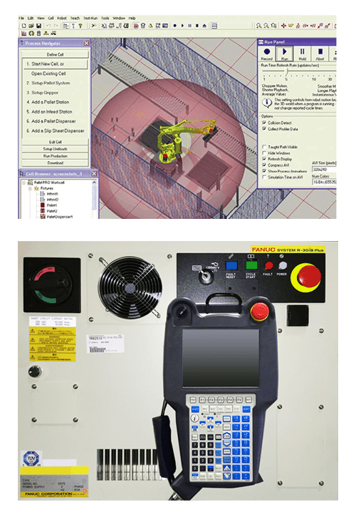
- Controller – hardware and software used to control the motion and communication of the robot and any components integrated into the system.
- Application software – Software specific to designing for your application-eg. palletizing.
- Teach Pendant – Input device used to program the robot.
- HMI – Graphic interface used by the system operators to run the system
- Other needed communication devices
Components
A variety of other components need to be added to the system to move the parts from one location to another and present the product to the robot.
- Conveying System – There are a wide variety of conveyors and conveyor add-ons to improve the speed of the product moving through the process. The integrator can help to select the proper type of conveyor for your application and facility.
- Sensors, actuators, other communication devices – these make sure the process is safe and accurate.
- End of Arm tooling/grippers – There are many factors that come in to play when designing an end of arm tool, such as part shape and material, pick and place point locations, production rate, product size and shape, quantity of parts to be handled with a single tool. Some types of grippers are listed below – read more here.
- Simple Pneumatics (Vacuum cup)
- Airflow/Foam Grippers
- Mechanical grippers
- Magnetic grippers
- Combination Gripper
- Easy tool changers
- Part presentation – How will the parts be presented to the robot for the EOAT to pick? Do you need a bowl feeder, bin, conveyor, pick station, stand…etc.
Up next is the final stage in this series, helping you get your employees ready for robotics. This not only means the operators’ training but how to explain changes the robots will bring to the work environment.
* If you want to review the other articles in the series, click on the area below to read the article.